I wanted to add some lighting to my 3d printer so that I could see the status of the bed heating and to shed some light on the build platform.
I went with these RGB strip lights from Amazon.com, they can be driven by a 12v power source and have a convenient adhesive backing which makes it easy to mount anywhere. Also make sure you order non-waterproof led lights since they cost less… unless you plan to 3d print in the rain.
Here’s a link to the RGB light strip I used:
http://amzn.to/1GMLXTC
I also needed 2 T0-220 Mosfets to allow the Rumba board to control the led lights without getting zapped. The pwm pins on an arduino can only handle a maximum current of 40ma, using mosfets is necessary since the LEDs can draw more current than that.
Here’s a link to the type of Mosfets that I used:
Wiring instructions for connecting the mosfets between your Rumba board and the led strip can be found here:
https://learn.adafruit.com/rgb-led-strips/usage
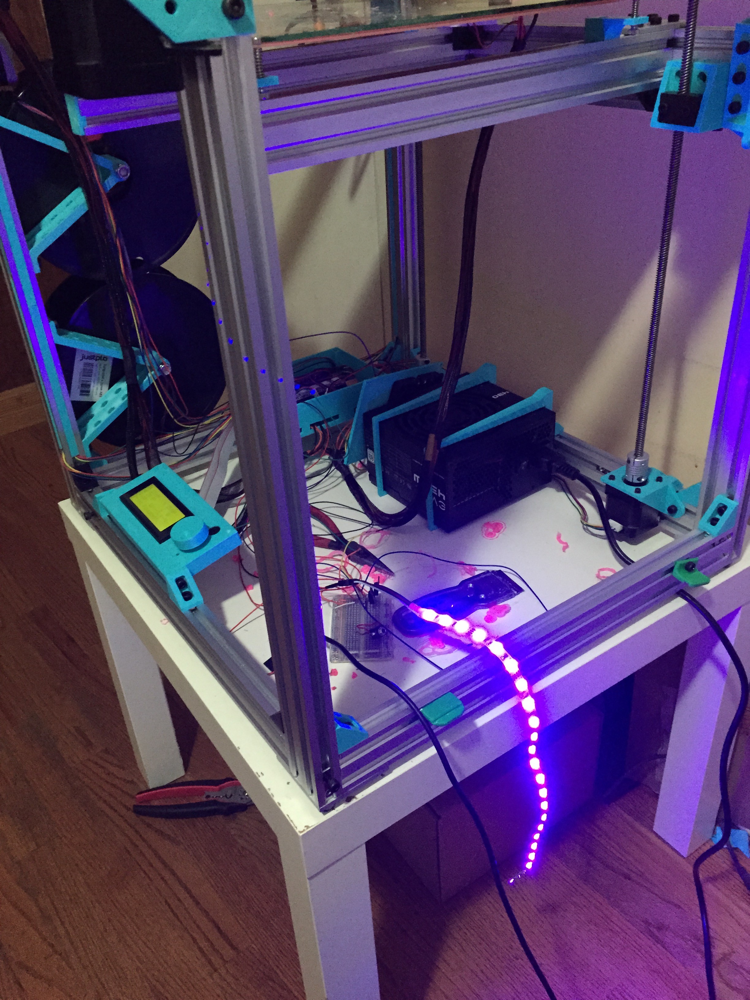
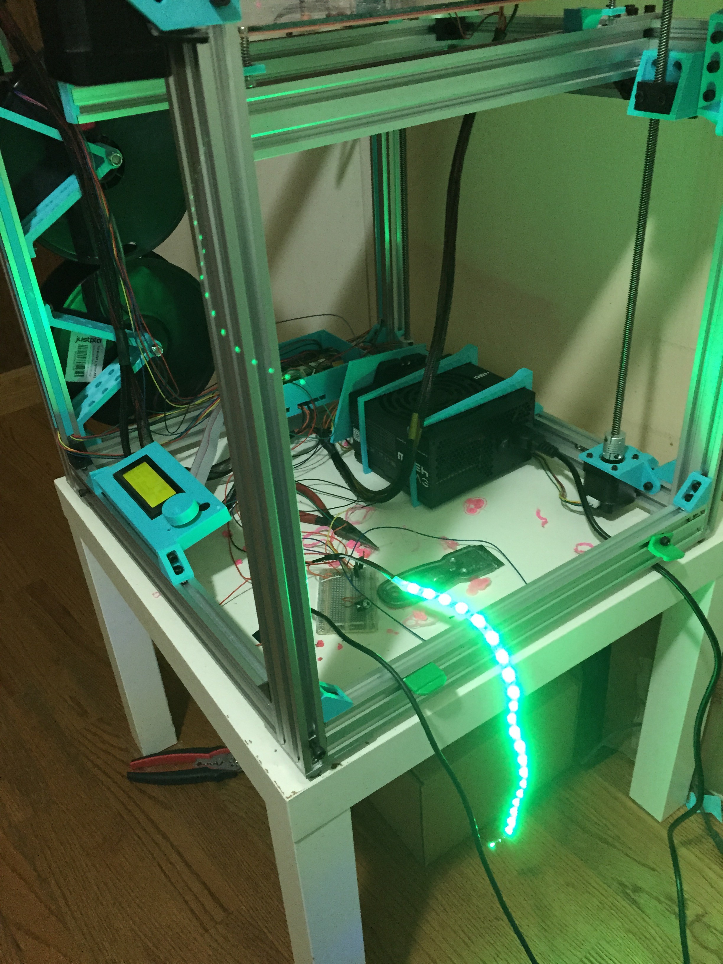
I used only 14″ of the RGB LEDs and I have plenty leftover for other projects. I mounted the LED strip using the adhesive already mounted on the back of the strip.
To modify my Marlin firmware I followed the instructions on this page here:
https://ultimaker.com/en/community/view/7204-rgb-led-strips-control
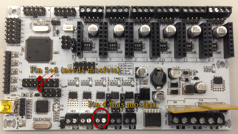
The hard part for me was finding which pins I could use on the RUMBA board and what their pin numbers were. I ended up plugging the power lead of the RGB LED strip into the + side of HE2 and the RGB Green wire to the – side of HE2 on the RUMBA. The pin number for HE2 is “4”. The HE2 port already has a MOSFET on it so no need for extra wiring there.
The other two pwm pins you can use on the RUMBA are on the expansion port called EXP3 and are pins 5 and 6. Look at the image below and realize the EXP3 port is ONLY the two rows of 7 pins on the left and does NOT include the two pins under the label “12V”. This confused me at first and I was connecting to the wrong pins.
Where to find the extra pwm pins!
When I enter M420 S0 and send it to the printer the LED strip pulses through all the colors of the rainbow, and it looks pretty cool!

Now that I had my LED lights wired up and able to be activated with Gcode commands, I now wanted it to gradually change from yellow to red as my build platform heated up. To do this I modified my Marlin_main.cpp with the following snippet of code. I modified the function gcode_M190() with the lines in bold below.
  inline void gcode_M190() {

    LCD_MESSAGEPGM(MSG_BED_HEATING);

    no_wait_for_cooling = code_seen('S');

    if (no_wait_for_cooling || code_seen('R'))

      setTargetBed(code_value());
millis_t temp_ms = millis();
cancel_heatup = false;
target_direction = isHeatingBed(); // true if heating, false if cooling
while ((target_direction && !cancel_heatup) ? isHeatingBed() : isCoolingBed() && !no_wait_for_cooling) {
millis_t ms = millis();
if (ms > temp_ms + 1000UL) { //Print Temp Reading every 1 second while heating up.
temp_ms = ms;
float tt = degHotend(active_extruder);
SERIAL_PROTOCOLPGM("T:");
SERIAL_PROTOCOL(tt);
SERIAL_PROTOCOLPGM(" E:");
SERIAL_PROTOCOL((int)active_extruder);
SERIAL_PROTOCOLPGM(" B:");
SERIAL_PROTOCOL_F(degBed(), 1);
-
setToRGB(255,255-(degBed()*2.318),0); //ADD THIS LINE-Yellow to Red as bed heats
SERIAL_EOL;
}
manage_heater();
manage_inactivity();
lcd_update();
}
LCD_MESSAGEPGM(MSG_BED_DONE);
-
setToRGB(255,255,255);//ADD THIS LINE-show white light after bed is done
refresh_cmd_timeout();
}